Centralized traffic filtering using AWS Network Firewall
In the process of constructing your Hybrid Hub and Spoke Network within the Cloud, which includes the integration of On-Premises networks and allows internet-based access, the implementation of a network firewall is essential for robust security. This security measure involves thorough traffic analysis and filtering between the entities to safeguard against both internal and external cyber threats and exploits. By actively monitoring and inspecting the flow of traffic, a network firewall plays a crucial role in identifying and blocking vulnerability exploits and unauthorized access attempts.
Within the AWS ecosystem, the AWS Network Firewall is a service that is often used for achieving a high level of network security. As a stateful and fully managed network firewall, it includes intrusion detection and prevention capabilities, offering comprehensive protection for VPC-based network traffic.
This blog post aims to guide you through the process of integrating the AWS Network Firewall into your hybrid AWS Hub and Spoke network. By doing so, you can effectively analyze, monitor, and filter both incoming and outgoing network traffic among all involved parties, thereby enhancing the overall security of your infrastructure layer.
Architecture
I would like to start by introducing the infrastructure that we are going to deploy as part of this blog post. The architecture diagram below provides a high-level snapshot of the components and workflow we are about to implement. Our objective is to build a Hybrid Hub and Spoke Network topology including a centralized AWS Network Firewall to conduct comprehensive network traffic analysis and filtering.
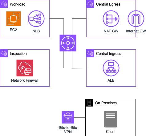
The Hub and Spoke network is designed with four Virtual Private Clouds (VPCs) interconnected through a Transit Gateway. The primary VPC, referred to as the Workload VPC, serves as the home for our enterprise workload. In this example, an Apache web server is deployed, accessible both from the On-Premises network and the Internet. Two additional VPCs, namely Central Ingress and Central Egress, are established to segregate incoming and outgoing traffic.
Within the Central Ingress VPC, an Application Load Balancer is configured to forward incoming requests from the Internet to the web server hosted in the Workload VPC. The Central Egress VPC allows the connectivity of the EC2 instance within the Workload VPC to the Internet, enabling the download of necessary packages and software.
To ensure comprehensive security, all traffic, including communication between different entities and in all directions, is monitored by the AWS Network Firewall. This security infrastructure is implemented within the Inspection VPC.
Additionally, an On-Premises location, housing clients seeking access to the web server through the private network, is integrated into the Hub and Spoke network via an AWS Site-to-Site VPN connection. For the purposes of this illustration, the On-Premises VPN connection will be configured and emulated using an AWS Virtual Private Cloud (VPC) in tandem with an EC2 instance operating StrongSwan. The traffic between the web server and the On-Premises clients is also routed through the Inspection VPC, allowing for continuous monitoring and filtering of data.
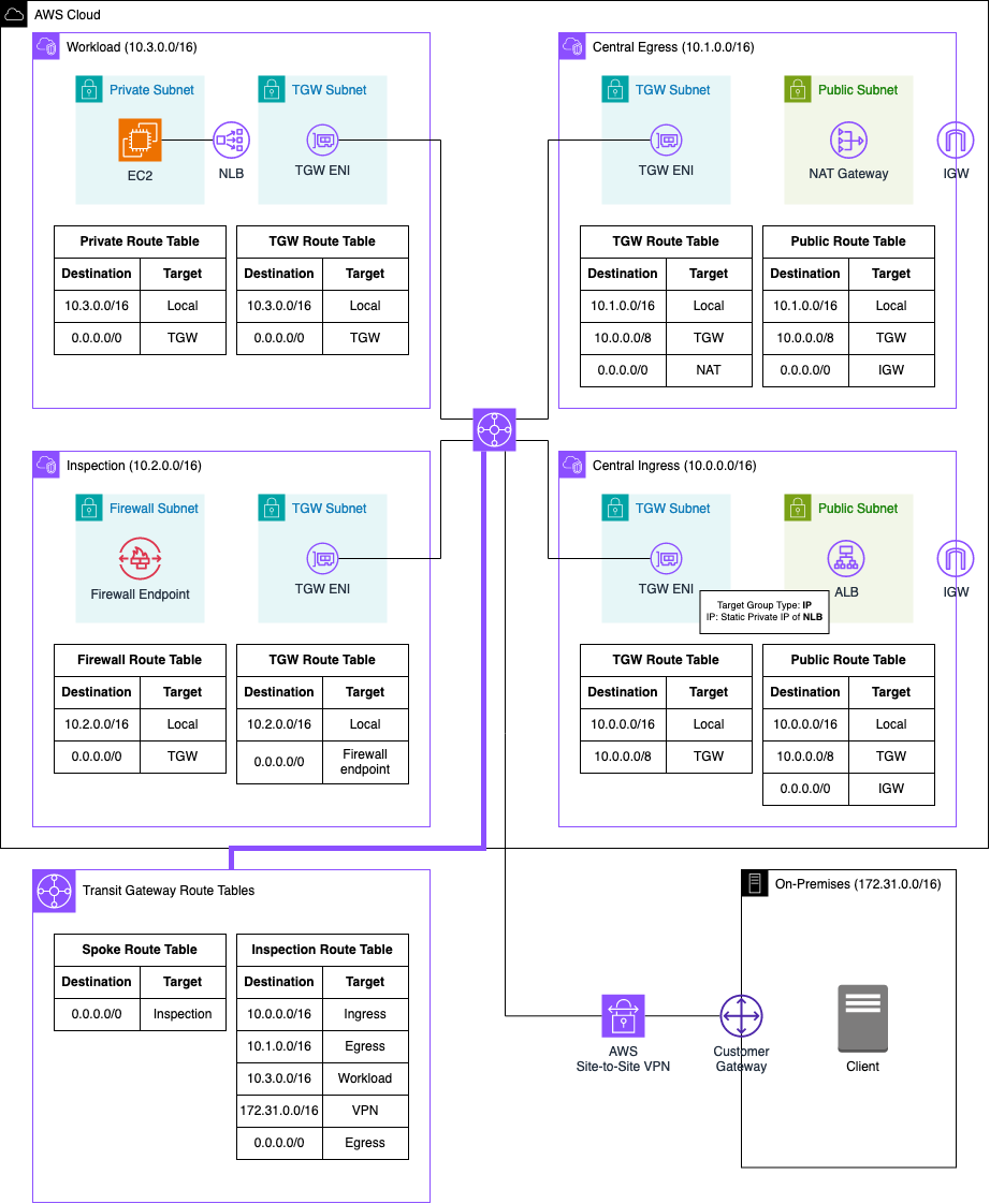
Below is an enhanced depiction of the architecture, presenting a more detailed diagram featuring the specific components to be deployed, along with Subnet and Transit Gateway routing tables for comprehensive understanding.
Traffic Flow
After having given a quick overview of the Hub and Spoke topology, we will make a deep dive into the different traffic flows that will be analysed as part of this example. The digramm below highlights the traffic flow permutations that we will encounter.
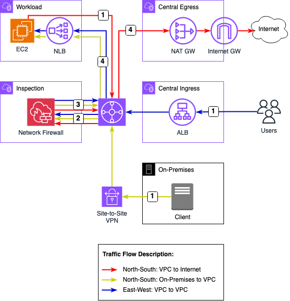
We will encounter three distinct flows as part of the example. North-South: VPC egress to Internet, North-South: On-Premises to VPC, and East-West: VPC to VPC.
North-South: VPC egress to Internet
-
Following the deployment of our infrastructure, the EC2 instance in the Workload VPC initiates the download of necessary packages and software essential for operating our Apache web server. The traffic exits the Workload VPC and is directed to the Transit Gateway. The subsequent forwarding of this traffic is determined by the associated Transit Gateway Route Table linked with the VPC attachment.
-
The outbound traffic flows to the Inspection VPC and, therefore, to the Network Firewall. This configuration enables thorough analysis and filtering of outgoing traffic. We have the flexibility to impose restrictions based on specific criteria, such as domain names. For instance, internet access can be limited only to hostnames provided by the Server Name Indication (SNI).
-
Upon completion of the outgoing traffic analysis, if no filtering occurs as per the network firewall rules, the traffic is routed back to the Transit Gateway. The following forwarding of this traffic is once again determined by the Transit Gateway Route Table linked with the VPC attachment.
-
Outbound traffic intended for the public Internet is directed to the Central Egress VPC. Within this VPC, the traffic is routed through a NAT Gateway, proceeding to an Internet Gateway, and finally reaching its destination in the public Internet. The return traffic follows the same route as the outbound traffic, allowing for analysis of traffic and comprehensive filtering of return traffic.
North-South: On-Premises to VPC
-
Once the Apache web server is operational, clients within our On-Premises network can initiate access attempts to the web server. These clients will connect to the web server via the internal Network Load Balancer. Traffic from the client is directed to the Transit Gateway through the AWS Site-to-Site VPN connection. The Transit Gateway VPN attachment is associated with a specific route table, which dictates the subsequent routing decisions.
-
The incoming traffic is directed to the Inspection VPC and the Network Firewall for thorough analysis and filtering based on the configured firewall settings. The AWS Network Firewall provides extensive flexibility, supporting both self-managed and AWS-managed firewall rules, allowing us to filter traffic based on a myriad of criteria.
-
Following the analysis of incoming traffic, if no filtering occurs as dictated by the network firewall rules, the traffic is routed back to the Transit Gateway. The subsequent forwarding of this traffic is determined once again by the Transit Gateway Route Table linked with the associated VPC attachment.
-
Incoming traffic bound for the web server is routed to the Workload VPC and directed to the Network Load Balancer, which in turn forwards the requests to the EC2 server hosting the web server. The return traffic follows the same route as the outbound traffic, enabling a detailed analysis of traffic and comprehensive filtering of return traffic.
East-West: VPC to VPC
-
With the Apache web server operational, external clients on the Internet can initiate access attempts through an Application Load Balancer sitting in the Central Ingress VPC. This Load Balancer actively listens for incoming requests and forwards traffic to the web server. Given that the web server resides in a separate VPC, the traffic is initially routed through the Transit Gateway. The subsequent forwarding of this traffic is determined by the associated Transit Gateway Route Table linked with the VPC attachment.
-
The incoming traffic is directed to the Inspection VPC and the Network Firewall for thorough analysis and filtering based on the configured firewall settings. The AWS Network Firewall provides extensive flexibility, supporting both self-managed and AWS-managed firewall rules, allowing us to filter traffic based on a myriad of criteria.
-
Following the analysis of incoming traffic, if no filtering occurs as dictated by the network firewall rules, the traffic is routed back to the Transit Gateway. The subsequent forwarding of this traffic is determined once again by the Transit Gateway Route Table linked with the associated VPC attachment.
-
Incoming traffic bound for the web server is routed to the Workload VPC and directed to the Network Load Balancer, which in turn forwards the requests to the EC2 server hosting the web server. The return traffic follows the same route as the outbound traffic, enabling a detailed analysis of traffic and comprehensive filtering of return traffic.
Bootstrap Environment
The code associated with this blog post is hosted on GitHub. You are welcome to either clone the repository or manually copy the code to your local machine. In the provided directory, you will discover two distinct folders. The network folder encapsulates the entire Terraform configuration for the Hub and Spoke Network, including the On-Premises network and VPN connection. The modules folder serves as the repository for Terraform modules that play an important role in our overarching Hub and Spoke Terraform configuration.
There are no adjustments to be made at this moment. Execute terraform init to initialize the Terraform providers, and then use terraform apply to deploy the infrastructure. Once the entire infrastructure has been successfully deployed, we will proceed to analyze the various methods available for accessing our web server.
Test Web Server Access
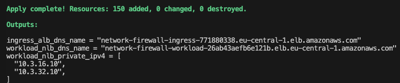
Initially, we’ll assess access from the public Internet. To reach the web server, submit a request to the Application Load Balancer. Extract the Load Balancer’s DNS name from the Terraform output ingress_alb_dns_name.
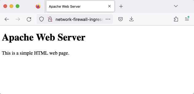
Input this domain into a web browser, hit enter, and confirm the successful access to the web server via the Central Ingress VPC through the displayed sample HTML page.
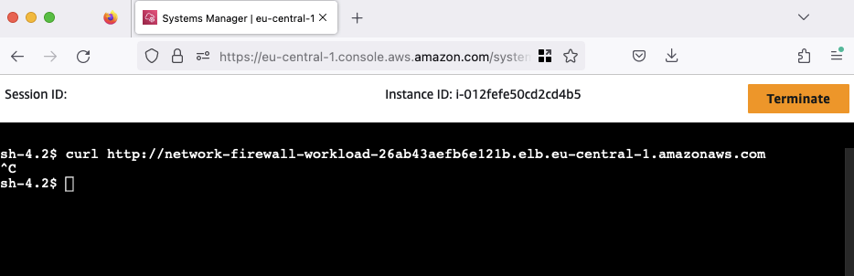
Next, we’ll verify access to the web server from the On-Premises location using the private network connection. Navigate to the AWS EC2 Console, select the network-firewall-traffic-analysis-on-prem-client EC2 instance, click on Connect, choose the Session Manager tab, and click Connect. After connecting to the instance via the Session Manager, execute a curl command to the private Network Load Balancer (NLB) endpoint. Extract the NLB’s DNS name from the Terraform output workload_nlb_dns_name.
You’ll observe that the connection cannot be established, resulting in no response. This is attributed to the current blocking of the connection between the On-Premises network and AWS by our Network Firewall. To resolve this issue, make a swift adjustment in the Terraform configuration.
Open the file terraform.tfvars, locate the variable network_firewall_on_premises_action, and change its value from DROP to PASS.
################################################################################
# General
################################################################################

application_name       = "network-firewall-traffic-analysis"
on_premises_cidr_range = "172.31.0.0/16"
aws_cidr_range         = "10.0.0.0/8"

network_firewall_on_premises_action = "PASS"
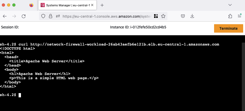
Execute terraform apply to implement the changes. Upon successful application, retry the request. This time, the On-Premises client’s request should succeed.
The connection tests from both the Internet and the On-Premises client to our web server have been successful. Feel free to customize the Network Firewall rules according to your preferences. For rule adjustments, you have the flexibility to utilize either the AWS console or the Terraform configuration The rule configurations are located in the inspection.tf file, providing a straightforward way for customization based on your specific requirements.
################################################################################
# Network Firewall Rule Group
################################################################################

resource "aws_networkfirewall_rule_group" "this" {
  capacity = 100
  name     = var.application_name
  type     = "STATEFUL"

  rule_group {
    rule_variables {
      ip_sets {
        key = "NLB_WORKLOAD"
        ip_set {
          definition = [for value in local.nlb_private_ipv4_addresses_list : "${value}/32"]
        }
      }

      ip_sets {
        key = "HOME_NET"
        ip_set {
          definition = [var.aws_cidr_range]
        }
      }

      ip_sets {
        key = "ON_PREM_NET"
        ip_set {
          definition = [var.on_premises_cidr_range]
        }
      }

      port_sets {
        key = "HTTP"
        port_set {
          definition = [80]
        }
      }
    }

    rules_source {
      stateful_rule {

        action = var.network_firewall_on_premises_action
        header {
          destination      = "$HOME_NET"
          destination_port = "ANY"
          direction        = "FORWARD"
          protocol         = "IP"
          source           = "$ON_PREM_NET"
          source_port      = "ANY"
        }
        rule_option {
          keyword  = "sid"
          settings = ["2"]
        }
      }
      stateful_rule {

        action = "PASS"
        header {
          destination      = "ANY"
          destination_port = "ANY"
          direction        = "FORWARD"
          protocol         = "IP"
          source           = "$HOME_NET"
          source_port      = "ANY"
        }
        rule_option {
          keyword  = "sid"
          settings = ["1"]
        }
      }
    }
  }
}
Once you are finished your experiments, run terraform deploy to destroy the AWS infrastructure.
Summary
The implemented architecture serves as a foundational example, and there are various ways to enhance its security and efficiency. You are encouraged to leverage this setup as a baseline, with the flexibility to tailor Network Firewall rules to their specific preferences. Experiment with writing firewall rules in Suricata format or try the implementation of egress restrictions based on hostnames to enhance the overall security posture according to your individual requirements. This adaptability ensures that the architecture can be fine-tuned to meet specific needs and evolving security considerations.
I hope you had fun and learned something new while working through this example. I am looking forward to your feedback and questions. If you want to take a look at the complete example code please visit my Github.
This blog post drew significant inspiration from Benjamin Trunnels’ article titled Deploy centralized traffic filtering using AWS Network Firewall
— Hendrik