Multiple Site-to-Site VPN Connections in AWS Hub and Spoke Topology
When setting up an IPSec VPN connection between your AWS network and your corporate data center, the fully-managed AWS Site-to-Site VPN service is a popular choice that often comes to mind. AWS Site-to-Site VPN offers a highly-available, scalable, and secure way to connect your on-premises users and workloads to AWS.
In this blog post, I would like to show you how you can go beyond a simple, static AWS Site-to-Site VPN connection by leveraging dynamically routed Site-to-Site VPNs in combination with a Transit Gateway. This hub and spoke network setup will allow us to employ the Border Gateway Protocol (BGP) as well as equal-cost multi-path routing (ECMP) and AWS Global Accelerator to not only exchange routing information between AWS and the corporate data center automatically but also increases the overall VPN throughput and reliability.
Introduction
When migrating to or setting up infrastructure on AWS, there is usually the need to communicate with systems that are currently running on-premises. While using the public Internet to exchange information might work for some workloads, business-critical workloads often require a secure and encrypted connection between peers due to strict company policies or industry regulations. One solution that is often employed to establish a connection between AWS and on-premises locations is a Site-to-Site IPSec VPN connection.
Site-to-Site IPSec VPNs ensure that personal and business data is encrypted, IP addresses are masked and communication over the Internet remains anonymous to the outside. As Site-to-Site VPNs create an encrypted tunnel between internal networks over the public Internet, external traffic can be simply blocked and access control of internal users to certain resources can be defined more clearly.
When setting up a Site-to-Site VPN between AWS and on-premises networks, the AWS Site-to-Site VPN service is the first and obvious choice. AWS Site-to-Site VPNs offer many benefits compared to self-managed solutions like VPN appliances installed on EC2 instances. Due to being a fully-managed solution, AWS Site-to-Site VPNs are highly-available, scalable and allow extensive monitoring by integrating with CloudWatch. While a simple, static AWS Site-to-Site VPN connection can be implemented relatively quickly and already offers the customers a lot of value and functionality, this setup can be enhanced by introducing a few additional AWS services and AWS Site-to-Site VPN features.
Firstly, by leveraging dynamically routed Site-to-Site VPNs instead of statically configured connections, we can employ the Border Gateway Protocol (BGP) protocol. BGP is a protocol that allows us to dynamically exchange routing and reachability information between autonomous systems (AS). In our case, BGP can be used to automatically exchange routing information between the AWS network and the cooperate data center. This eliminates the need to statically configure routes in AWS and on-premises and allows for a more flexible and extensible setup.
Secondly, we can utilize a Transit Gateway to attach the AWS Site-to-Site VPN instead of a Virtual Private Gateway that is connected to a single VPC. By using a Transit Gateway in combination with a VPN connection we can not only make use of the hub and spoke functionality to interconnect multiple AWS VPCs and cooperate networks, but also leverage features like equal-cost multi-path routing (ECMP) and AWS Global Accelerator to make our infrastructure more robust and performant.
By default, AWS Site-to-Site VPN connections can achieve a throughput of 1.25 Gbps. ECMP can be used to get a higher VPN bandwidth by aggregating multiple VPN tunnels and is currently only supported when using AWS Transit Gateway. Furthermore, a VPN connection can use AWS Global Accelerator to route traffic from the cooperate data center to the closest AWS edge location. This option helps to prevent network disruptions caused by using the public internet and ensures that traffic reaches the AWS internal network as soon as possible.
Architecture
Before we start the actual implementation, I would like to guide you through the architecture we are planning to deploy as part of this example. The diagram below displays a high-level overview of the setup we are trying to simulate.
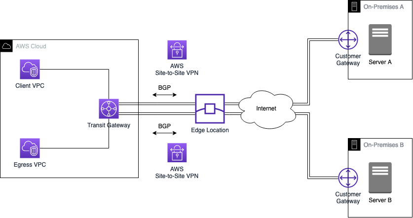
The goal is to create an IPSec Site-to-Site VPN tunnel between AWS and two On-Premises networks. We will leverage AWS Site-to-Site VPNs to create the connections in combination with AWS Global Accelerator to implement a highly available and performant VPN solution. To create a hub and spoke network topology and increase the performance of our VPNs, we will use AWS Transit Gateway and ECMP. Furthermore, we will use BGP to dynamically exchange routes between AWS and the On-Premises data centers. This setup will allow us to establish reliable and secure communication between all parties. The diagram below displays the target architecture in greater detail.
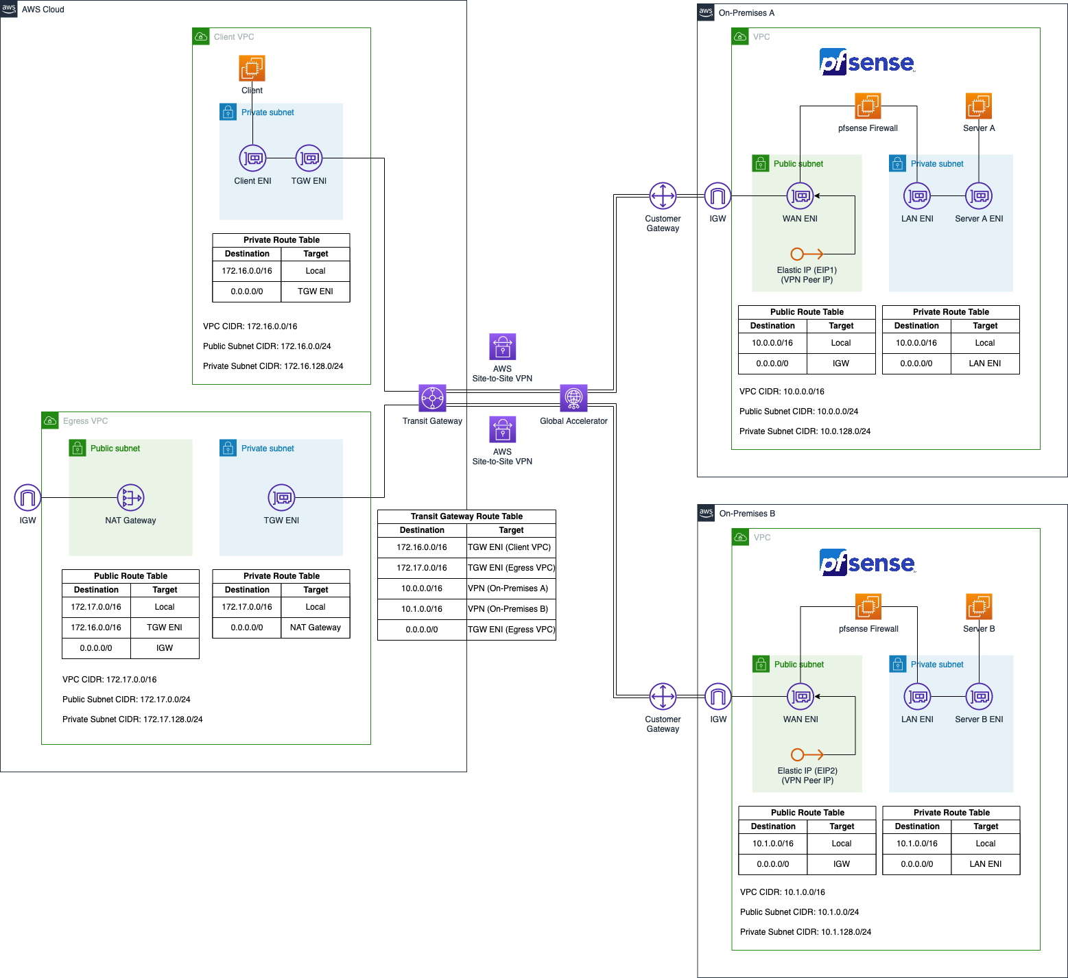
We will set up four VPCs in AWS. The VPCs Client VPC and Egress VPC on the left-hand side will represent the AWS network while the two VPCs on the right-hand side will simulate the on-premises network On-Premises A and On-Premises B. Both the on-premises networks will be connected to the AWS network using AWS Site-to-Site VPN tunnels.
The Client VPC will consist of a single private subnet and will house a single application server that needs to communicate with both the on-premises networks as well as the public Internet via the Egress VPC. The centralized Egress VPC will consist of two subnets. A private subnet as well as a public subnet. A NAT Gateway will be present in the public subnet to allow the applications located in private subnets to communicate with the public Internet.
The setup of the two on-premises VPC will be identical in nature. Each environment will consist of a VPC with two subnets, a private and a public subnet. The private subnet will contain a server that the client in the Client VPC needs to reach. The public subnet will contain the pfSense appliance that we will use to create a Site-to-Site VPN connection between the AWS network and our simulated on-premises setup.
The pfSense EC2 instance will have two Elastic Network Interfaces, a LAN ENI as well as a WAN ENI. The LAN ENI will be placed in the corresponding private subnet of each VPC and will allow EC2 instances running in the private subnets to forward VPN traffic to the virtual appliance. The LAN ENI will only be assigned a private IP address. The WAN ENI will be placed in the public subnet of the VPCs and will function as the entry point to the networks. Besides the private IPs, they will also be assigned a static public IP each by using Elastic IPs. The public IPs will be used as the VPN Peer IPs and will allow the creation of an IPSec VPN connection between the two VPCs.
In order to create a hub and spoke network and allow communication between all parties, we will leverage AWS Transit Gateway. The Transit Gateway will be attached to both the Client VPC and the Egress VPC directly via Transit Gateway VPC Attachments. To establish a connection to the on-premises networks, AWS Site-to-Site VPN Attachments will be used. We will leverage both ECMP and AWS Global Accelerator in combination with the Transit Gateway to increase the throughput and reliability of our VPN connections. Routes between AWS and the on-premises networks will be exchanged via BGP.
Even though this solution is meant to give you an overview of how to create a Site-to-Site IPSec VPN between AWS and on-premises networks, the code can also be leveraged to create a secure tunnel between two AWS VPCs.
Project Structure
Before we start setting up our Terraform configuration, I would like you to create the project structure. Please create the following files and folders.
├── aws
│   ├── locals.tf
│   ├── client.tf
│   ├── tgw.tf
│   ├── vpc_client.tf
│   ├── vpc_egress.tf
│   ├── terraform.tfvars
│   ├── variables.tf
│   └── outputs.tf
├── eip
│   ├── eip.tf
│   └── outputs.tf
├── modules
│   └── on-prem-bootstrap
└── on-premises
    ├── main.tf
    ├── terraform.tfvars
    └── variables.tf
As this example will be quite extensive, we will split up our Terraform configuration into separate files and folders. The Terraform configuration for the AWS network will be contained in the aws folder while the configuration for the on-premises networks will be contained in the on-premises folder. The folder eip will be used to separately deploy the Elastic IPs for the VPN peer IPs. The module on-prem-bootstrap contains code that will be used to bootstrap both on-premises networks.
Request Elastic IPs for Public Encryption Domain
Before we can deploy both the AWS and on-premises VPCs, there are a few steps we need to take first.
First, we will have to create the two Elastic IPs for the VPN Peer IPs. These IPs will be assigned to the pfSense appliances and will be used during the creation of the AWS Customer Gateway objects. Please copy the following snippet into the eip/eip.tf.
resource "aws_eip" "on_premises_1_peer_ip" {
  domain = "vpc"
}

resource "aws_eip" "on_premises_2_peer_ip" {
  domain = "vpc"
}
To get the IP address values, add the following outputs to the eip/outputs.tf.
output "on_premises_1_peer_ip" {
  description = "IP of the On-Premises 1 VPN Peer"
  value       = aws_eip.on_premises_1_peer_ip.public_ip
}

output "on_premises_2_peer_ip" {
  description = "IP of the On-Premises 2 VPN Peer"
  value       = aws_eip.on_premises_2_peer_ip.public_ip
}
Go into the folder eip and run terraform init and terraform apply to deploy the infrastructure. Right down the IP addresses that were created. They will be used later during the Site-to-Site VPN setup to define the Customer Gateway objects.
In the case of this example, the EIPs that were created had the following values. These IPs will be used later on when we configure the virtual VPN appliances. You will recognize the IPs in the screenshots that are used to visualize the configuration steps. Please REPLACE these IPs with the EIPs you created in the section above. Your example will NOT work otherwise.
on_premises_1_peer_ip = 3.78.208.128
on_premises_2_peer_ip = 54.93.217.168
Subscribe to Marketplace Images
After having created the two EIPs for the Peer IPs, we have to subscribe to the Marketplace images of the virtual appliance we are going to use. As discussed earlier, we will leverage pfSense to function as the on-premises endpoint for our AWS Site-to-Site VPN connections. Feel free to use a different appliance if you feel comfortable.
Visit the official link and start the subscription process.
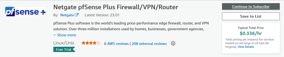
Netgate offers a 30 trial for this AMI. During this time, there will be no software charges for the use of the AMI by Netgate. AWS infrastructure charges will still apply.
After having subscribed to the image, you will be able to use the pfSense AMI in the Terraform configuration.
Deploy AWS Cloud VPC
Let’s continue by creating the AWS network VPCs and all their components.
Network Deployment
We will start by deploying the AWS network infrastructure. The VPCs and all included components will be the basis for the EC2 instance as well as the Transit Gateway and the AWS Site-to-Site VPN connection. The Terraform configuration for the aws/vpc_client.tf can be found here. The Terraform configuration for the aws/vpc_egress.tf can be found here.
Next, we will define the Terraform configuration for our Transit Gateway and the AWS Site-to-Site VPN connections. Please copy the following code into aws/tgw.tf.
################################################################################
# Transit Gateway
################################################################################

resource "aws_ec2_transit_gateway" "this" {
  amazon_side_asn = "64512"
  vpn_ecmp_support = "enable"
}

resource "aws_ec2_transit_gateway_vpc_attachment" "client" {
  subnet_ids         = local.private_subnet_ids_client
  transit_gateway_id = aws_ec2_transit_gateway.this.id
  vpc_id             = aws_vpc.client.id
}

resource "aws_ec2_transit_gateway_vpc_attachment" "egress" {
  subnet_ids         = local.private_subnet_ids_egress
  transit_gateway_id = aws_ec2_transit_gateway.this.id
  vpc_id             = aws_vpc.egress.id
}


################################################################################
# Site-to-Site VPN connections
################################################################################

resource "aws_customer_gateway" "this" {
  for_each = var.on_premises_networks

  bgp_asn    = each.value.bgp_asn
  ip_address = each.value.customer_gateway_ip
  type       = "ipsec.1"

  tags = {
    Name = each.key
  }
}

resource "aws_vpn_connection" "this" {
  for_each = aws_customer_gateway.this

  customer_gateway_id = each.value.id
  transit_gateway_id  = aws_ec2_transit_gateway.this.id
  type                = each.value.type
  enable_acceleration = true

  local_ipv4_network_cidr  = var.on_premises_networks[each.key].cidr_range
  remote_ipv4_network_cidr = var.vpc_cidr_block_client
}


################################################################################
# Default Route
################################################################################

resource "aws_ec2_transit_gateway_route" "this" {
  destination_cidr_block         = "0.0.0.0/0"
  transit_gateway_attachment_id  = aws_ec2_transit_gateway_vpc_attachment.egress.id
  transit_gateway_route_table_id = aws_ec2_transit_gateway.this.association_default_route_table_id
}
The Transit Gateway we will deploy has ECMP support enabled and will be connected to the two AWS VPC via VPC Attachments. Additionally, we will create two Customer Gateways for our Site-to-Site VPN. A Customer Gateway maps onto a physical or software appliance that is managed in the on-premises network. In our case, the Customer Gateway will map onto the pfSense appliance. The VPN connections will have AWS Global Accelerator enabled to ensure a more stable connection between the AWS and on-premises network. Finally, we will create a static default route in our Transit Gateway route table to ensure that traffic to the public Internet will be routed to the centralized Egress VPC.
Before we are able to deploy our network, we have to define a few variables and local values for our VPCs. We will start with defining the variables. Please copy the following snippet into the aws/variables.tf. Besides the variables for the VPC CIDR blocks, we already included a variable for the application_name, availability_zones, and a map of objects for the on_premises_networks. Each object will represent an on-premises environment.
variable "vpc_cidr_block_client" {
  description = "CIDR of vpc"
  type        = string
}

variable "vpc_cidr_block_egress" {
  description = "CIDR of vpc"
  type        = string
}

variable "availability_zones" {
  description = "AZ to deploy network to"
  type        = list(string)
  default     = ["eu-central-1a"]
}

variable "application_name" {
  description = "Name of the application"
  type        = string
}

variable "on_premises_networks" {
  description = "Map of On-Premises networks to connect to"
  type = map(object({
    customer_gateway_ip = string
    cidr_range          = string
    bgp_asn             = number
  }))
}
To manage the values of our defined variables, we will create a aws/terraform.tfvars file. This will help us to keep our Terraform configuration clean and readable. Please define the following values for our variables in the terraform.tfvars file. For customer_gateway_ip in each on_premises_networks object, please enter the corresponding EIPs we created in the section above.
vpc_cidr_block_client = "172.16.0.0/16"
vpc_cidr_block_egress = "172.17.0.0/16"

application_name = "aws-site"

on_premises_networks = {
  on-premises-1 = {
    customer_gateway_ip = "xxxxxxxx"
    cidr_range          = "10.0.0.0/16"
    bgp_asn             = 65001
  }

  on-premises-2 = {
    customer_gateway_ip = "xxxxxxxx"
    cidr_range          = "10.1.0.0/16"
    bgp_asn             = 65002
  }
}
Based on the input values for the variables vpc_cidr_block_egress, vpc_cidr_block_client, and availability_zones, we will calculate the subnet ranges automatically using Terraform local values. Please copy the following Terraform configuration into aws/locals.tf.
locals {

  public_subnets_client = { for index, v in var.availability_zones : "subnet_${index}" =>
    {
      cidr_block        = cidrsubnet(var.vpc_cidr_block_client, 8, index)
      availability_zone = v
    }
  }

  private_subnets_client = { for index, v in var.availability_zones : "subnet_${index}" =>
    {
      cidr_block        = cidrsubnet(var.vpc_cidr_block_client, 8, index + 128)
      availability_zone = v
    }
  }

  public_subnets_egress = { for index, v in var.availability_zones : "subnet_${index}" =>
    {
      cidr_block        = cidrsubnet(var.vpc_cidr_block_egress, 8, index)
      availability_zone = v
    }
  }

  private_subnets_egress = { for index, v in var.availability_zones : "subnet_${index}" =>
    {
      cidr_block        = cidrsubnet(var.vpc_cidr_block_egress, 8, index + 128)
      availability_zone = v
    }
  }

  private_subnet_ids_client   = [for k, v in aws_subnet.private_client : v.id]
  private_subnet_ids_egress   = [for k, v in aws_subnet.private_egress : v.id]
}
Go into the aws folder and let’s run terraform init to initialize Terraform and terraform apply to deploy the network infrastructure. Once Terraform has deployed the configuration, you should see a new network setup in the AWS console.
Client Deployment
The last thing to add before we can finish up the AWS Cloud VPC setup is the addition of the client EC2 instance. Please add the following Terraform configuration to the aws/client.tf.
################################################################################
# Client EC2
################################################################################

resource "aws_instance" "client" {
  instance_type          = "t3.micro"
  ami                    = data.aws_ami.amazon_2.id
  subnet_id              = local.private_subnet_ids_client[0]
  iam_instance_profile   = aws_iam_instance_profile.this.name
  vpc_security_group_ids = [aws_security_group.client.id]

  root_block_device {
    volume_size           = 8
    volume_type           = "gp3"
    encrypted             = true
    delete_on_termination = true
  }

  tags = { "Name" = "${var.application_name}-Client" }

}


################################################################################
# Get newest Linux 2 AMI
################################################################################

data "aws_ami" "amazon_2" {
  most_recent = true

  filter {
    name   = "name"
    values = ["amzn2-ami-hvm-*-x86_64-ebs"]
  }
  owners = ["amazon"]
}


################################################################################
# EC2 Instance Profile
################################################################################

resource "aws_iam_role" "this" {
  name = var.application_name

  assume_role_policy = jsonencode({
    Version = "2012-10-17"
    Statement = [
      {
        Action = "sts:AssumeRole"
        Effect = "Allow"
        Principal = {
          Service = "ec2.amazonaws.com"
        }
      },
    ]
  })
}

resource "aws_iam_instance_profile" "this" {
  name = "${aws_iam_role.this.name}-ip"
  role = aws_iam_role.this.name
}

resource "aws_iam_role_policy_attachment" "this" {
  role       = aws_iam_role.this.name
  policy_arn = "arn:aws:iam::aws:policy/AmazonSSMManagedInstanceCore"
}


################################################################################
# Client Security Group
################################################################################

resource "aws_security_group" "client" {
  name   = "${var.application_name}-client"
  vpc_id = aws_vpc.client.id
}

resource "aws_security_group_rule" "client_egress" {
  security_group_id = aws_security_group.client.id

  type        = "egress"
  from_port   = 0
  to_port     = 0
  protocol    = -1
  cidr_blocks = ["0.0.0.0/0"]
}


resource "aws_security_group_rule" "client_icmp_ingress" {
  security_group_id = aws_security_group.client.id

  type        = "ingress"
  from_port   = -1
  to_port     = -1
  protocol    = "icmp"
  cidr_blocks = [for value in var.on_premises_networks : value.cidr_range]
}
The client EC2 has received an Instance Profile. The Instance Profile is necessary to connect to the EC2 instance later on using the AWS System Manager Session Manager.
Before we deploy the client instance, we will add an output to our Terraform configuration. This output will provide all the values we will need later on during the pfSense appliance configuration. Let’s create the output source by adding the following configuration to the aws/locals.tf.
  vpn_output_map = { for key, value in aws_vpn_connection.this : key => {
    customer_gateway_peer_ip           = aws_customer_gateway.this[key].bgp_asn
    customer_gateway_asn               = aws_customer_gateway.this[key].ip_address
    tunnel1_address                    = value.tunnel1_address
    tunnel1_cgw_inside_address         = value.tunnel1_cgw_inside_address
    tunnel1_vgw_inside_address         = value.tunnel1_vgw_inside_address
    tunnel1_preshared_key              = value.tunnel1_preshared_key
    tunnel1_bgp_asn                    = value.tunnel1_bgp_asn
    tunnel2_address                    = value.tunnel2_address
    tunnel2_cgw_inside_address         = value.tunnel2_cgw_inside_address
    tunnel2_vgw_inside_address         = value.tunnel2_vgw_inside_address
    tunnel2_preshared_key              = value.tunnel2_preshared_key
    tunnel2_bgp_asn                    = value.tunnel2_bgp_asn
    customer_gateway_ipv4_network_cidr = value.local_ipv4_network_cidr
    aws_ipv4_network_cidr              = value.remote_ipv4_network_cidr
  } }
This map vpn_output_map contains an object of all the values we need in order to configure our pfSense appliance. Add the following snippet to the aws/outputs.tf in order to generate the Terraform output.
output "vpn_output_map" {
  description = "Output map containing all the necessary VPN information"
  value       = local.vpn_output_map
  sensitive   = true
}
Let’s run terraform apply in the aws folder to deploy the client EC2 instance. Once Terraform has deployed the configuration, you should see a new instance in the AWS console.
Deploy On-Premises VPCs
After having deployed the AWS network, we will create the on-premises VPCs and all their components. Please be aware, that we will use Terraform to deploy the infrastructure only. The actual configuration of the virtual appliance pfSense will be done later once everything has been deployed.
We will leverage an existing Terraform on-prem-bootstrap module to quickly deploy both on-premises environments. Please download the module from the Github repository of this blog post and copy it into the folder modules/on-prem-bootstrap. The module will create the whole on-premises infrastructure including VPC, pfSense appliance, and EC2 server based on a few input variables. We will start by creating the variables necessary. Please copy the following snippet into the on-premises/variables.tf.
variable "on_premises_networks" {
  description = "Input for On-Premises Terraform module"
  type = map(object({
    vpc_cidr_block                  = string
    opposite_on_premises_cidr_range = string
    aws_peer_ips                    = list(string)
    on_premises_peer_ip             = string
    })
  )
}

variable "aws_cidr_range" {
  description = "CIDR range of the AWS network"
  type        = string
}
To manage the values of our defined variables, we will create a on-premises/terraform.tfvars file. This will help us to keep our Terraform configuration clean and readable. Please define the following values for our variables in the on-premises/terraform.tfvars file. The on_premises_peer_ip value needs to be the AWS EIP we just created earlier and can be found in the Terraform output vpn_output_map.on-premises-1.customer_gateway_peer_ip and vpn_output_map.on-premises-2.customer_gateway_peer_ip. The aws_peer_ips are the public IPs that AWS provides as part of the AWS Site-to-Site VPN service. These values can also be found in the Terraform output vpn_output_map.on-premises-1.tunnel1_address and vpn_output_map.on-premises-1.tunnel2_address for the on-premises-1 and vpn_output_map.on-premises-2.tunnel1_address and vpn_output_map.on-premises-2.tunnel2_address for on-premises-2.
on_premises_networks = {
  on-premises-1 = {
    vpc_cidr_block                  = "10.0.0.0/16"
    opposite_on_premises_cidr_range = "10.1.0.0/16"
    aws_peer_ips                    = ["xxxxxxxx", "xxxxxxxx"]
    on_premises_peer_ip             = "xxxxxxxx"
  }
  on-premises-2 = {
    vpc_cidr_block                  = "10.1.0.0/16"
    opposite_on_premises_cidr_range = "10.0.0.0/16"
    aws_peer_ips                    = ["xxxxxxxx", "xxxxxxxx"]
    on_premises_peer_ip             = "xxxxxxxx"
  }
}

aws_cidr_range = "172.16.0.0/16"
As you can see, the only thing we have to define when setting up our on-premises networks using the provided module, are the AWS Client VPC CIDR range and the Terraform object for each network. Once we have defined the variables, we will continue by calling the module in order to create our services. Copy the following Terraform configuration into the on-premises/main.tf.
module "on_premises_network" {
  for_each = var.on_premises_networks

  source = "../modules/on-prem-bootstrap"

  application_name                = each.key
  vpc_cidr_block                  = each.value.vpc_cidr_block
  aws_cidr_range                  = var.aws_cidr_range
  opposite_on_premises_cidr_range = each.value.opposite_on_premises_cidr_range
  aws_peer_ips                    = each.value.aws_peer_ips
  on_premises_peer_ip             = each.value.on_premises_peer_ip

}
By leveraging the provided module, we are able to keep the Terraform configuration of our on-premises networks short and clean. The module will be called using the Terraform for_each statement to create multiple identical instances of the module. Go into the on-premises folder and run terraform init and terraform apply to deploy our infrastructure.
pfSense Configuration
After having deployed both on-premises VPCs, we will continue by configuring the pfSense appliances.
Please be aware that I will only show the configuration of the pfSense appliance for the On-Premises network A. The configuration for the second appliance is identical. You can follow the same steps described in this section to set up both appliances.
Login and System Preparation
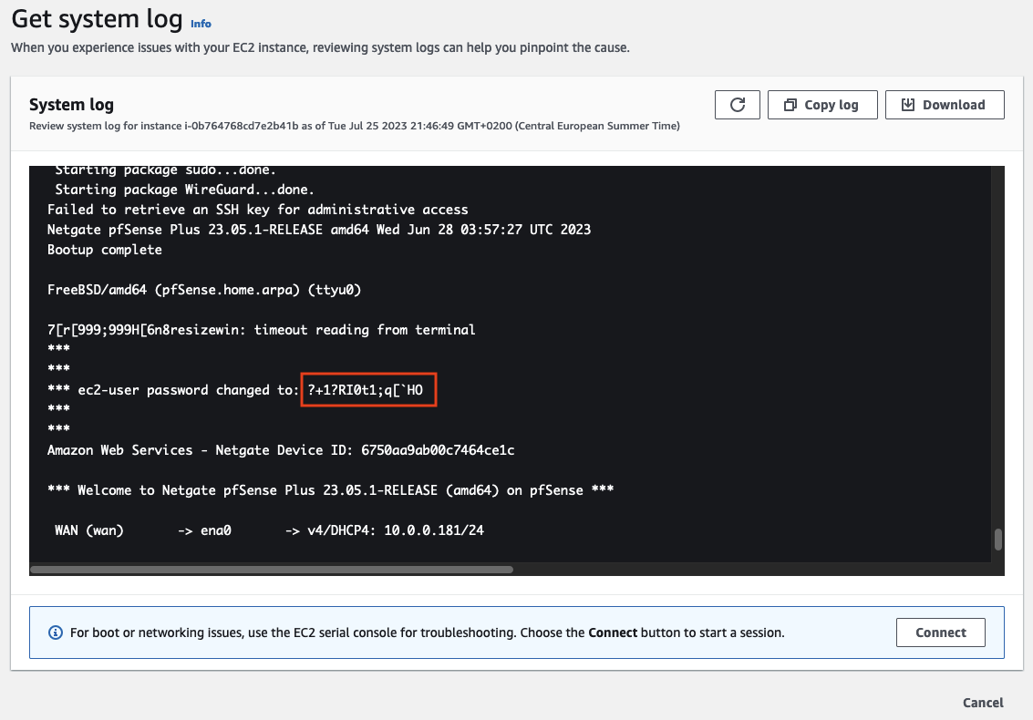
Before we are able to set up the appliances, we have to retrieve the passwords needed to log in. Open the AWS Console and navigate to the EC2 service screen. Right-click on the first instance running pfSense on-premises-1-pfSense, choose Monitor and troubleshoot, and select Get system log.
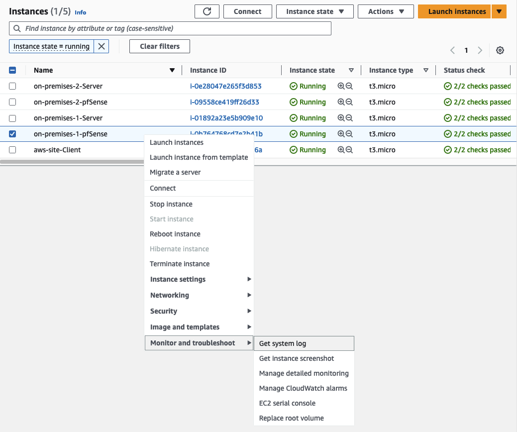
The system log will display the password that needs to be used to log in under ec2-user password changed to:
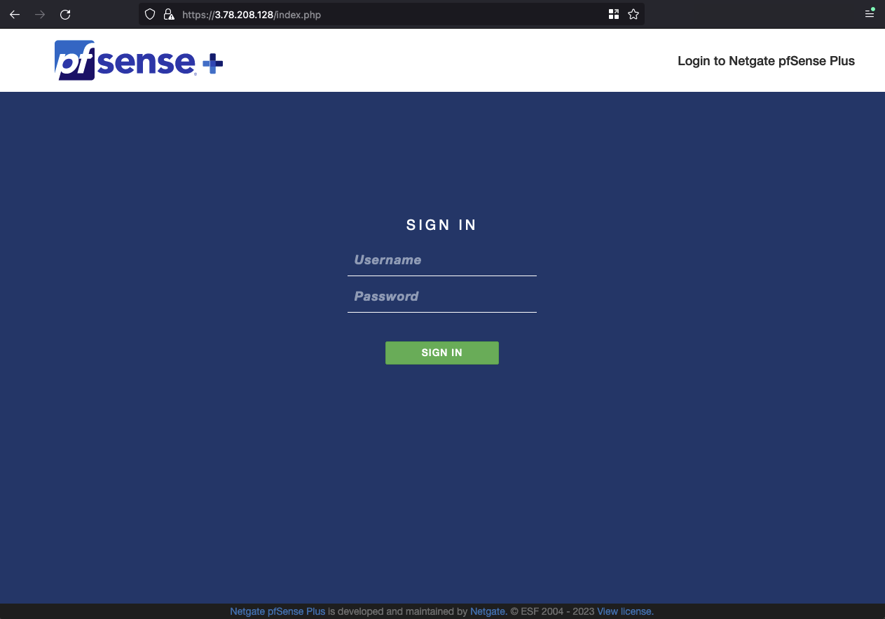
Once you have retrieved the password, log in to the pfSense WEB GUI. Open the GUI by typing https://ON-PREMISES-PEER-IP into the browser. Replace ON-PREMISES-PEER-IP with the EIP of the on-premises network A you created in the first section of this example. The login page should open. Type in the username admin and the password you just retrieved.
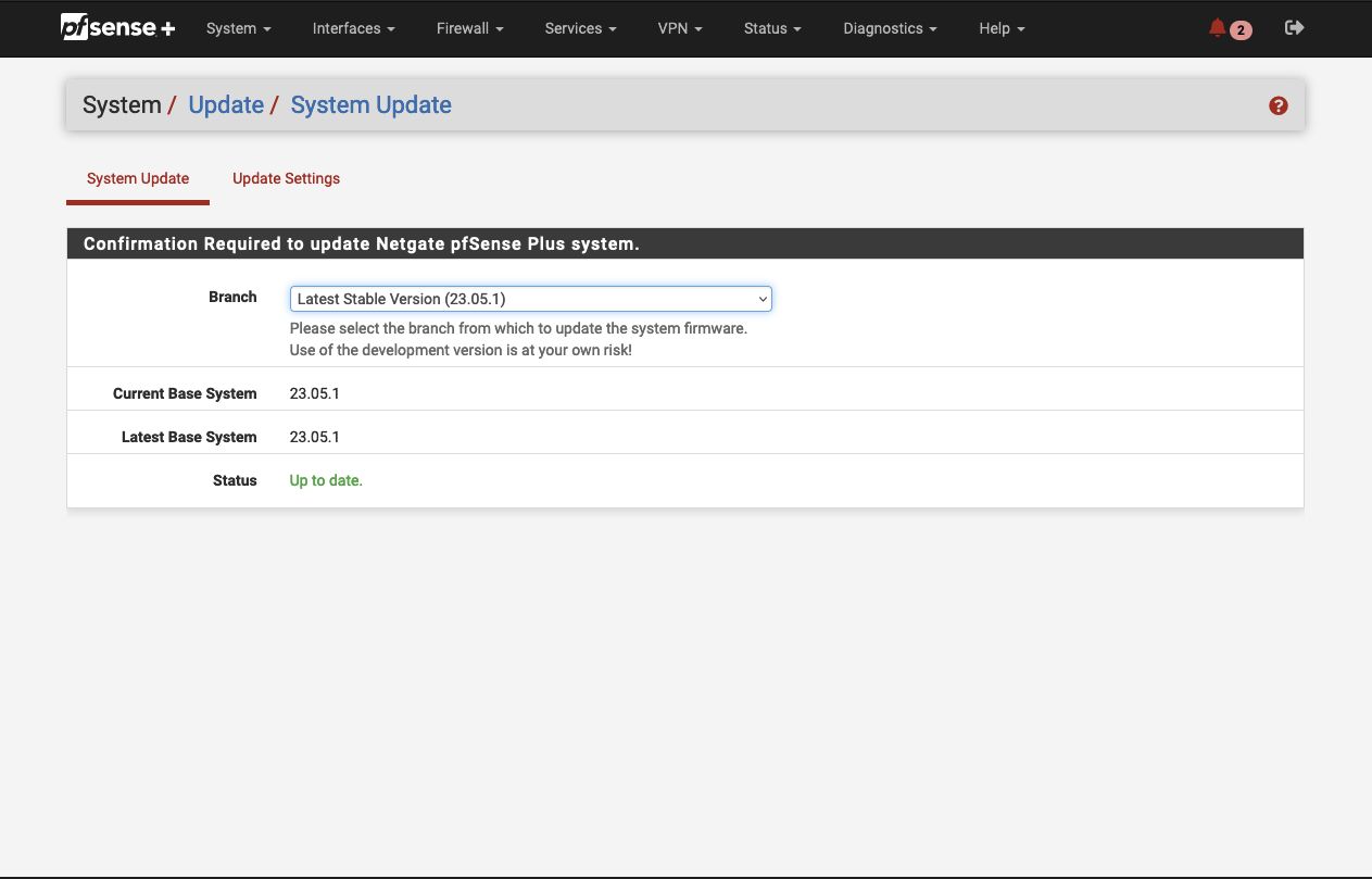
After having logged in, we will check for System Updates. Navigate to System -> Update -> System Update.
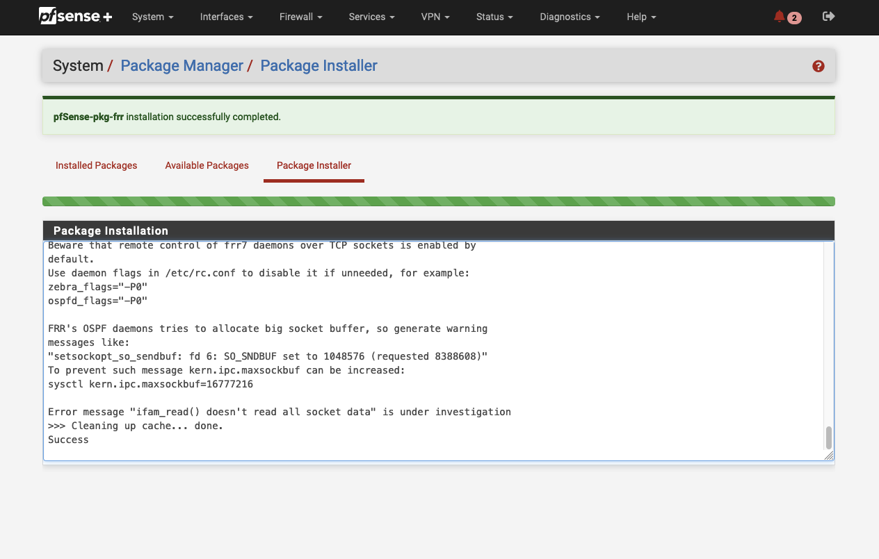
Afterward, we will install the package FRR using the inbuild package manager. The FRR package will allow us to manage dynamic routing via BGP once we have set up the IPSec VPN tunnel. Navigate to System -> Package Manager -> Available Packages and search for ‘frr’. Click on install next to the package to start the installation process.
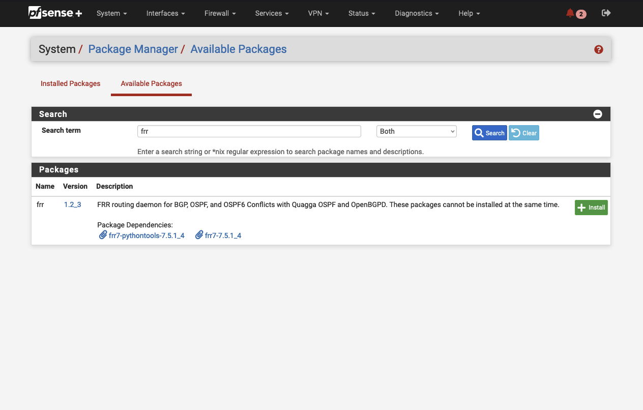
After a successful installation process, dynamic routing via BGP will be available in pfSense.
IPSec VPN Configuration
Continue by setting up the interface for the LAN ENI. Navigate to Interfaces -> Interface Assignments.
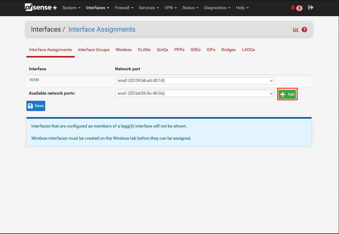
You should see the already created WAN interface. Click on Add to add an additional interface.
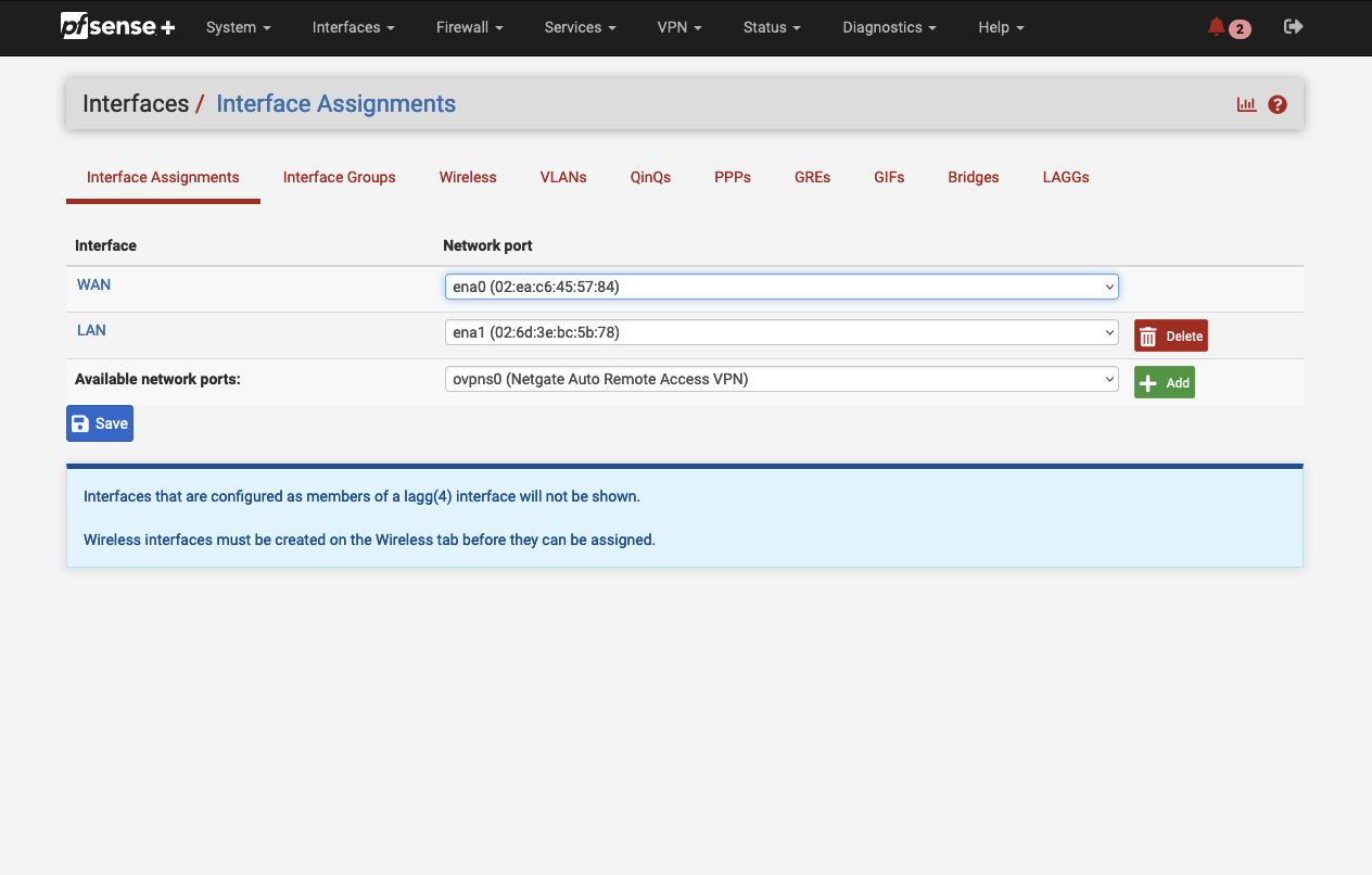
Once the Interface has been created, click on LAN. A new configuration window will open. Enable the interface by checking Enable and set the IPv4 Configuration Type to DHCP.
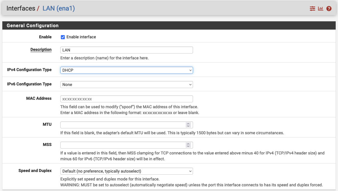
Confirm your configuration by clicking on Apply changes. After having created the LAN interface, it is time to
configure the on-premises connection of the Site-to-Site VPN. We will set up two VPN tunnels per appliance for redundancy.
All values needed for the VPN tunnel setup can be found in the Terraform output vpn_output_map.
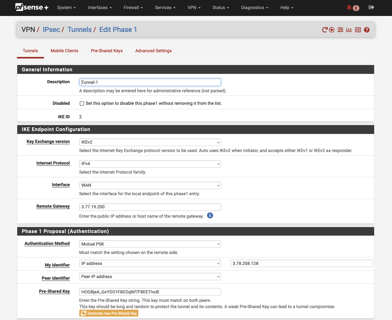
Navigate to VPN and click on IPsec. Click on Add P1 in the bottom left corner to create a new Phase 1. A new configuration window will open up.
Make sure the IKE Endpoint Configuration parameters are configured as followed.
| Field name | Value | Terraform Output |
|---|---|---|
| Key Exchange version | IKEv2 | |
| Internet Protocol | IPv4 | |
| Interface | WAN | |
| Remote Gateway | vpn_output_map.on-premises-1.tunnel1_address |
Under Phase 1 Proposal (Authentication) set the parameter My identifier to IP address and add the Elastic IP address of the pfSense instance (vpn_output_map.on-premises-1.customer_gateway_peer_ip). Enter the key (vpn_output_map.on-premises-1.tunnel1_preshared_key) generated by AWS under Pre-Shared Key. Click on Save to create a new Phase 1.
Next, we will create a corresponding Phase 2. Click on Show Phase 2 Entries to open up a new menu. Select Add P2 to create a new Phase 2. A new configuration window will open up.
Set the Mode to Routed (VTI) under General Information. Make sure the Networks parameters are configured as followed.
| Field name | Description | Terraform Output |
|---|---|---|
| Local Network | Customer Gateway Inside IP | vpn_output_map.on-premises-1.tunnel1_cgw_inside_address |
| Remote Network | Virtual Private Gateway Inside IP | vpn_output_map.on-premises-1.tunnel1_vgw_inside_address |
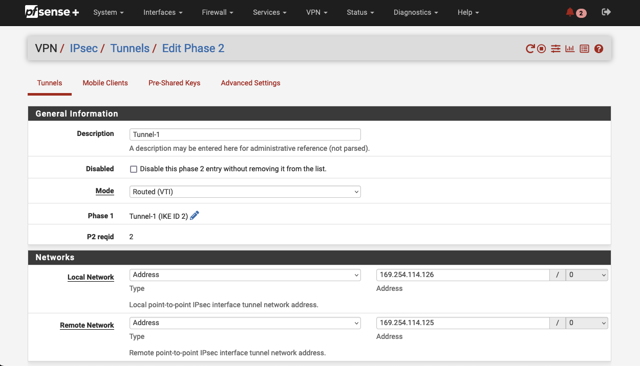
Click on Save to save the Phase 2 configuration. Confirm the configuration by clicking Apply Changes. We now have successfully set up the first tunnel (Tunnel 1) of the first Site-to-Site VPN connection.
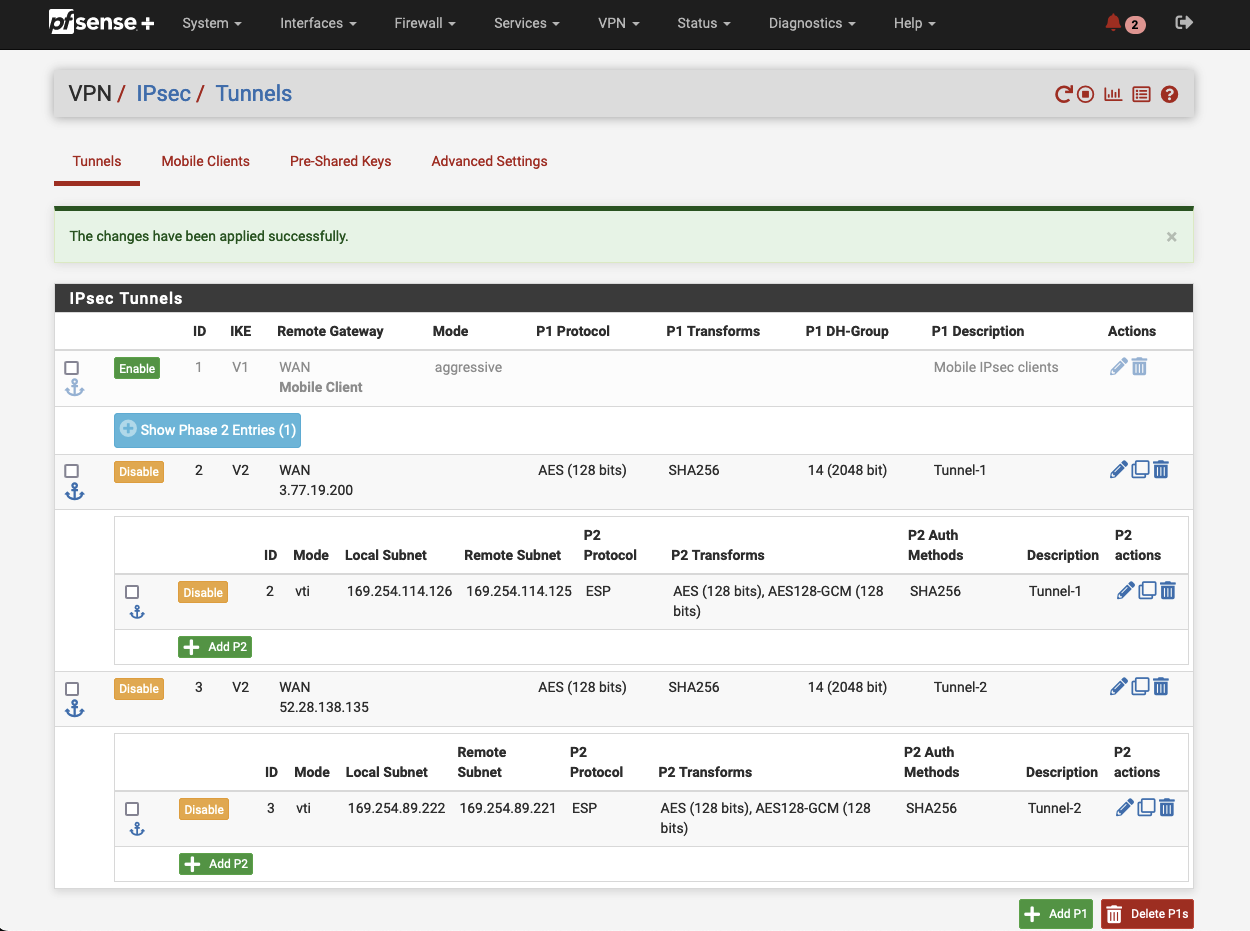
Please repeat the steps mentioned above to set up the second tunnel (Tunnel 2) of the first VPN connection. At the end of this configuration process, you should have two VPN tunnels set up and configured.
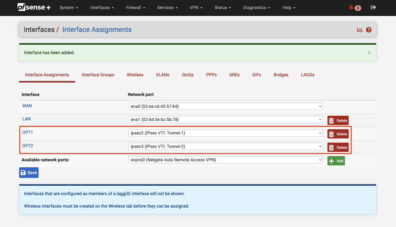
As we create both VPN tunnels using the mode Routed (VTI), we need to create two Virtual Tunnel Interfaces (VTI) before we can send traffic over the IPSec tunnel. An IPsec Virtual Tunnel Interface is a routable virtual interface type for terminating IPsec tunnels. Navigate to Interfaces -> Interface Assignments and select Add. A new VTI for tunnel 1 with the name OPT1 should appear in the console. Click on Add again in order to add a second VTI for the second tunnel. After having added both VTIs, click on each interface. Select Enable to enable the interface. Click Save and confirm your configuration by clicking on Apply changes.
Next, navigate to Status -> IPSec -> Overview. pfSense should display both IPSec VPN tunnels. Click on Connect P1 and P2 in order to establish the VPN connection between the AWS network and the VPN appliance. If everything has been configured correctly, you should see the message Established in the pfSense console.
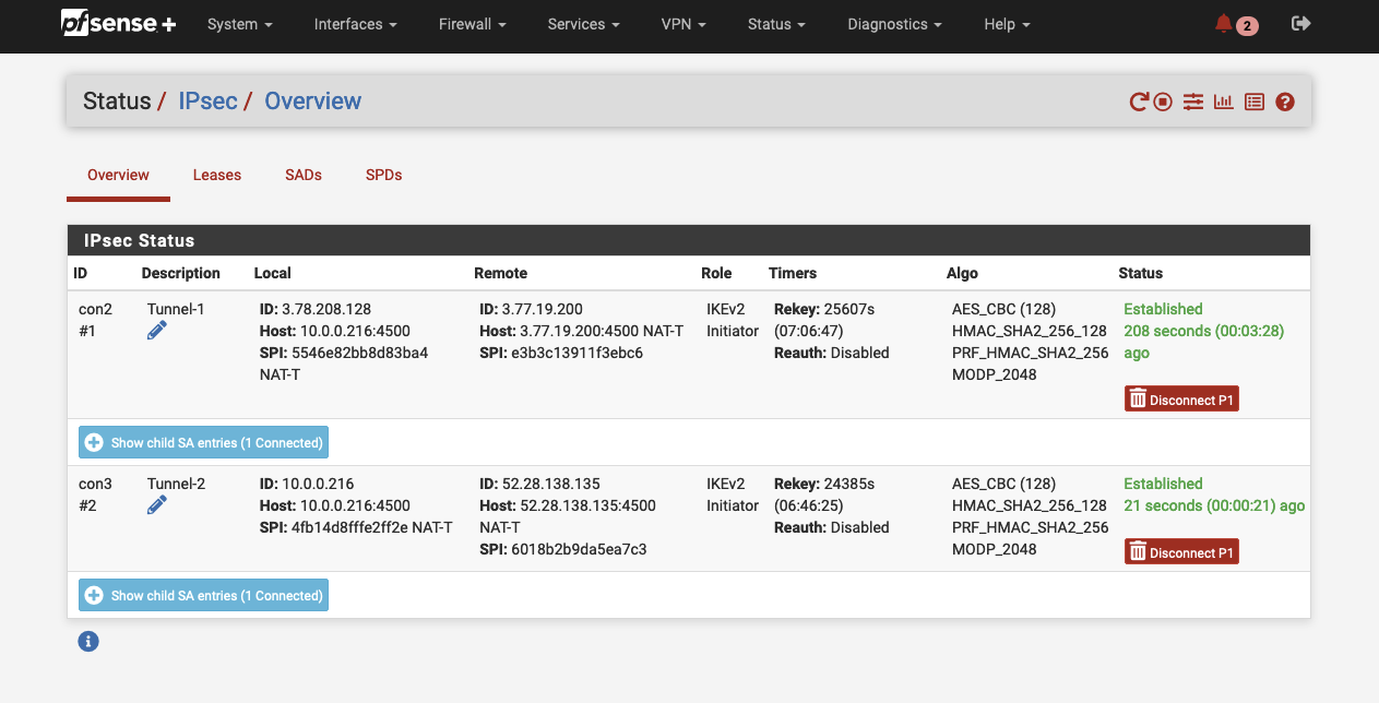
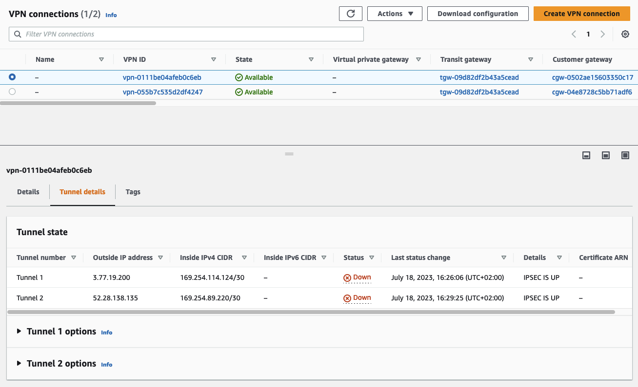
We will verify that the IPSec tunnels were successfully established via the AWS Console. Open the VPC service page, navigate to the tab Virtual private network (VPN), and click on Site-to-Site VPN connections. Select the Site-to-Site VPN that you just configured and select Tunnel details. The Status of both VPN tunnels should be Down while the Details fields will display the status IPSEC IS UP. This means that the IPSec tunnels were successfully established. In order to bring both tunnels from Down into the Up state, we will have to configure BGP in pfSense.
BGP Configuration
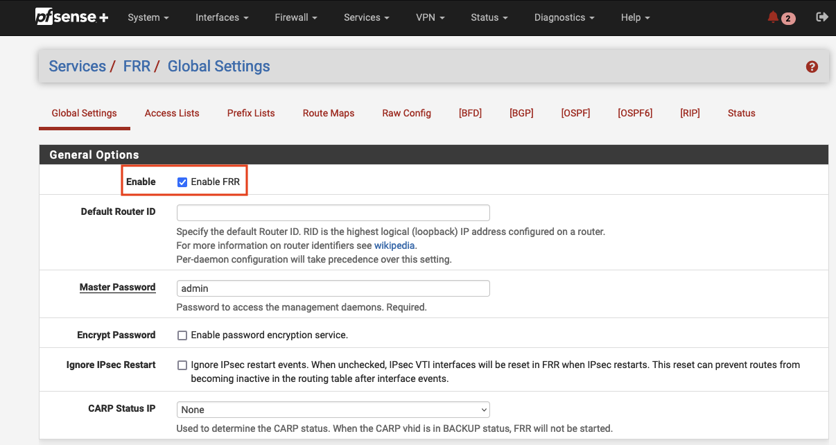
Now that we have configured both IPSec tunnels, it is time to configure BGP using the previously installed FRR package. In order to use FRR, we have to enable the service first. Navigate to Services -> FRR -> Global Settings and tick Enable FRR. Enter a Master Password and click on Save to save the settings.
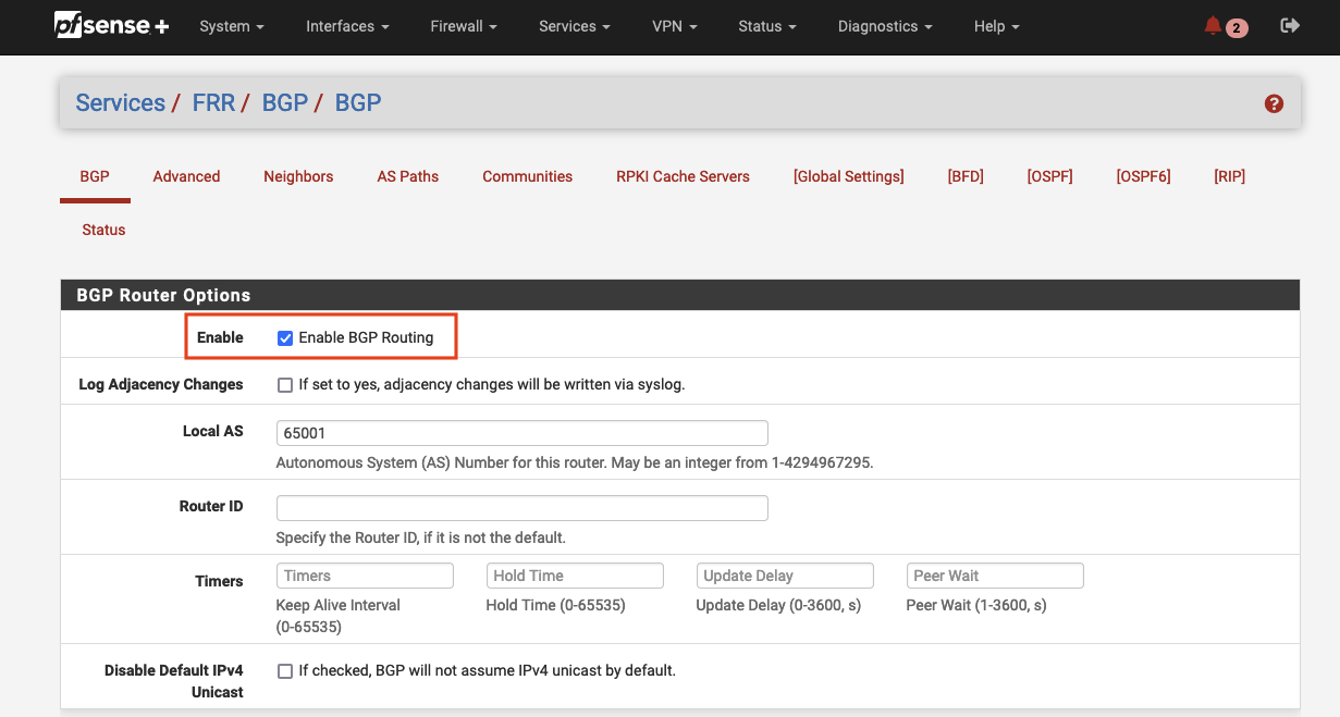
Once enabled, we will also have to enable BGP and define the Autonomous System (AS) number of the pfSense appliance. Navigate to Services -> FRR -> BGP -> BGP and tick Enable BGP Routing to enable BGP. Afterward, define the Local AS of the appliance. The value can be found in the Terraform output vpn_output_map.on-premises-1.customer_gateway_asn.
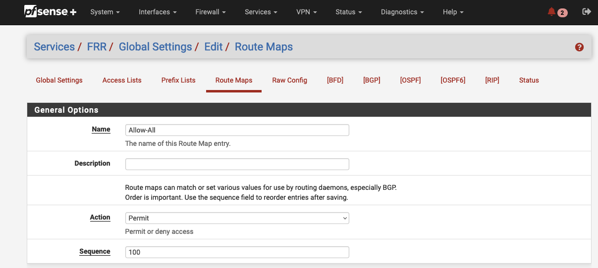
After having enabled BGP, we will create a Route Map. A route map allows you to define whether or not specific routes are accepted from BGP neighbors or distributed to neighbors. The matching process of route maps can be influenced based on criteria like ACLs or prefix lists. To keep this example as simple as possible, we will create a single route map that allows all traffic. We will use the route map later on when defining the BGP neighbors to allow inbound and outbound route exchange. Navigate to Services -> FRR -> Global Settings -> Route Maps and click on Add to create a new route map. A new configuration window will open up. Make sure the General Options parameters are configured as followed.
| Field name | Value |
|---|---|
| Name | Allow-All |
| Action | Permit |
| Sequence | 100 |
Click on Save to save the new route map.
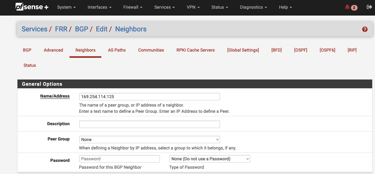
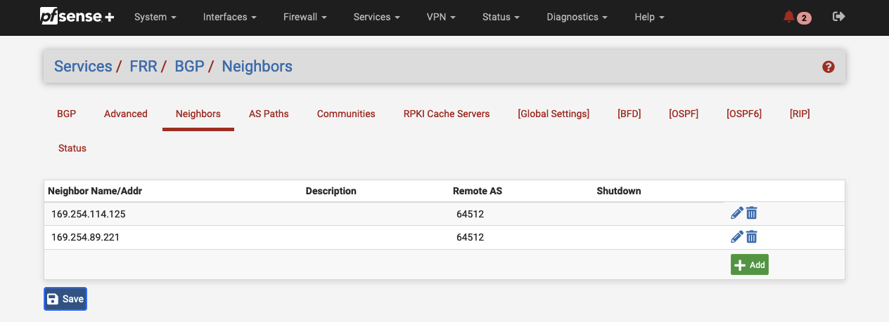
Next, we will define the BGP neighbors. We will create one neighbor for each IPSec tunnel that we implemented. Navigate to Services -> FRR -> BGP -> Neighbors and click on Add to create a new neighbor for the first tunnel (Tunnel 1). A new configuration window will open up. Configure the General Options parameters as followed.
| Field name | Description | Terraform Output |
|---|---|---|
| Name/Address | Virtual Private Gateway Inside IP | vpn_output_map.on-premises-1.tunnel1_vgw_inside_address |
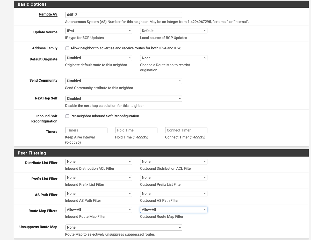
Set the Basic Options and Peer Filtering.
| Field name | Description | Terraform Output |
|---|---|---|
| Remote AS | AWS AS | vpn_output_map.on-premises-1.tunnel1_bgp_asn |
| Field name | Value |
|---|---|
| Route Map Filters | Allow-All |
Afterward, configure the Network Distribution.
| Field name | Value | Terraform Output |
|---|---|---|
| Network to Distribute => Subnet to Route | vpn_output_map.on-premises-1.tunnel1_vgw_inside_address | |
| Network to Distribute => Route Map | Allow-All |
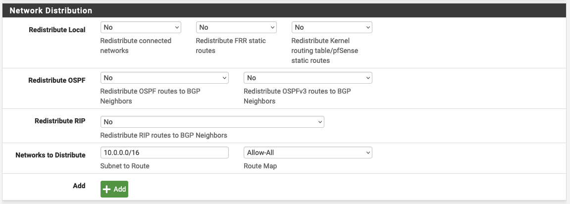
Click on Save to save the neighbor configuration.
Repeat the same process to set up a neighbor connection for the second VPN tunnel (Tunnel 2). Once both neighbors have been set up in pfSense, you should see two neighbors in the pfSense console.
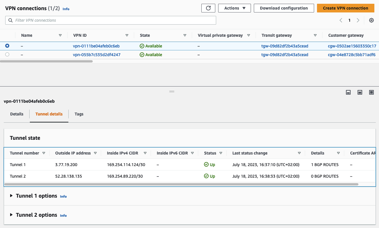
We will also verify that the BGP connections have been successfully established via the AWS console. Open the VPC service page, navigate to the tab Virtual private network (VPN), and click on Site-to-Site VPN connections. Select the Site-to-Site VPN that you just configured and select Tunnel details. The Status of both VPN tunnels should now be Up and the Details fields will display the status IPSEC IS UP. This means that both the BPG connection and the IPSec tunnels were successfully established.
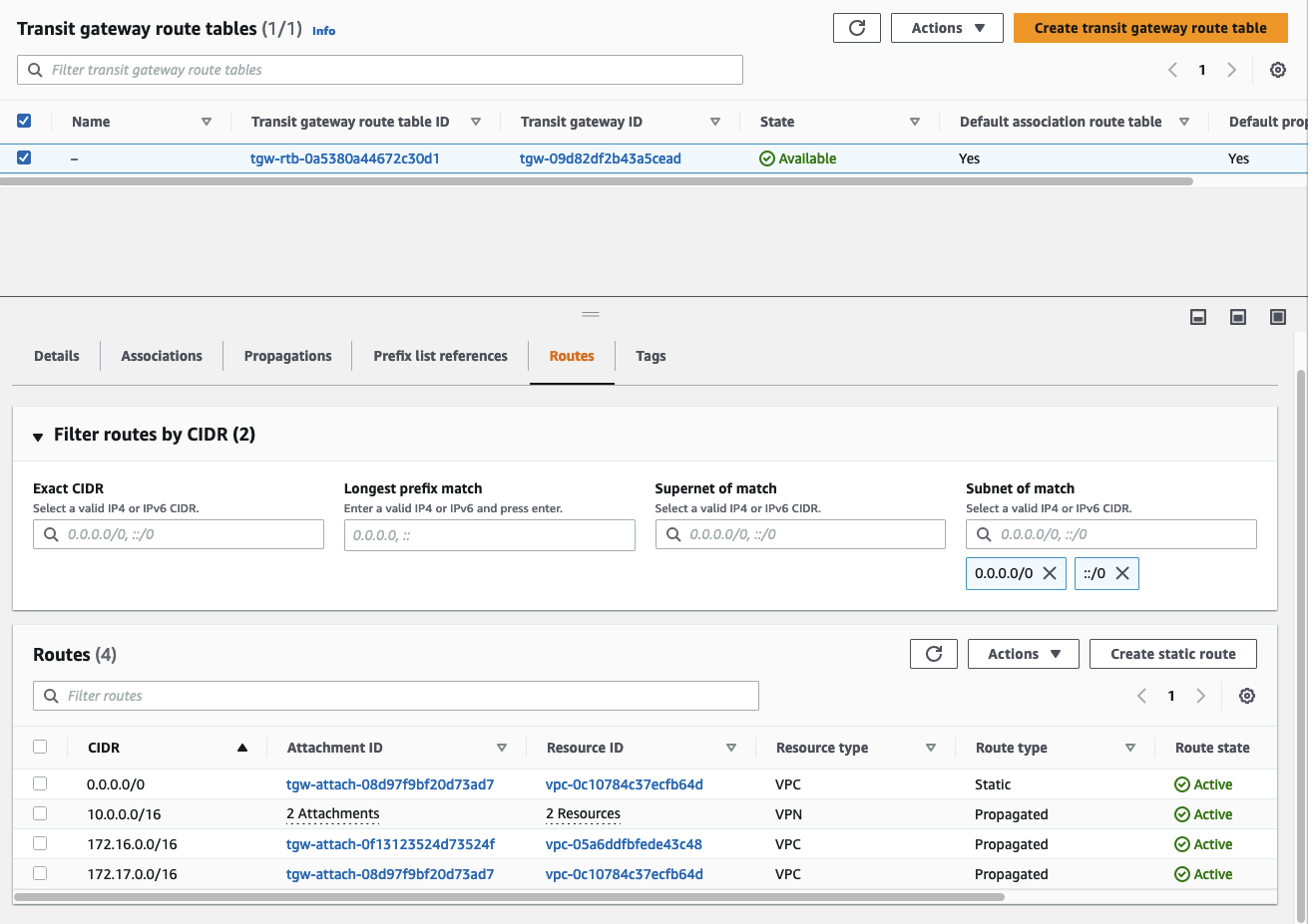
We will do one last verification before testing the client/server connection. Open the VPC service page, navigate to the tab Transit gateways, and click on Transit gateway route tables. Select the default Transit Gateway route table and select the tab Routes. If you have configured BGP correctly you should see, that the Transit Gateway route table was automatically populated. It will display the network range you configured in the pfSense appliance as Route type -> Propagated. This shows that the on-premises CIDR range was successfully advertised to the AWS network.
This section showed the configuration of the pfSense appliance for the On-Premises network A. Please repeat the section pfSense Configuration for the pfSense appliance of On-Premises network B in order to establish a Site-to-Site VPN connection between AWS and both on-premises networks.
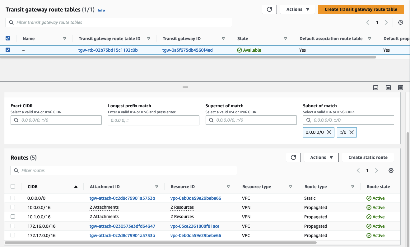
Once you have set up both pfSense appliances, you should see both on-premises network CIDR ranges being propagated to the Transit Gateway route table.
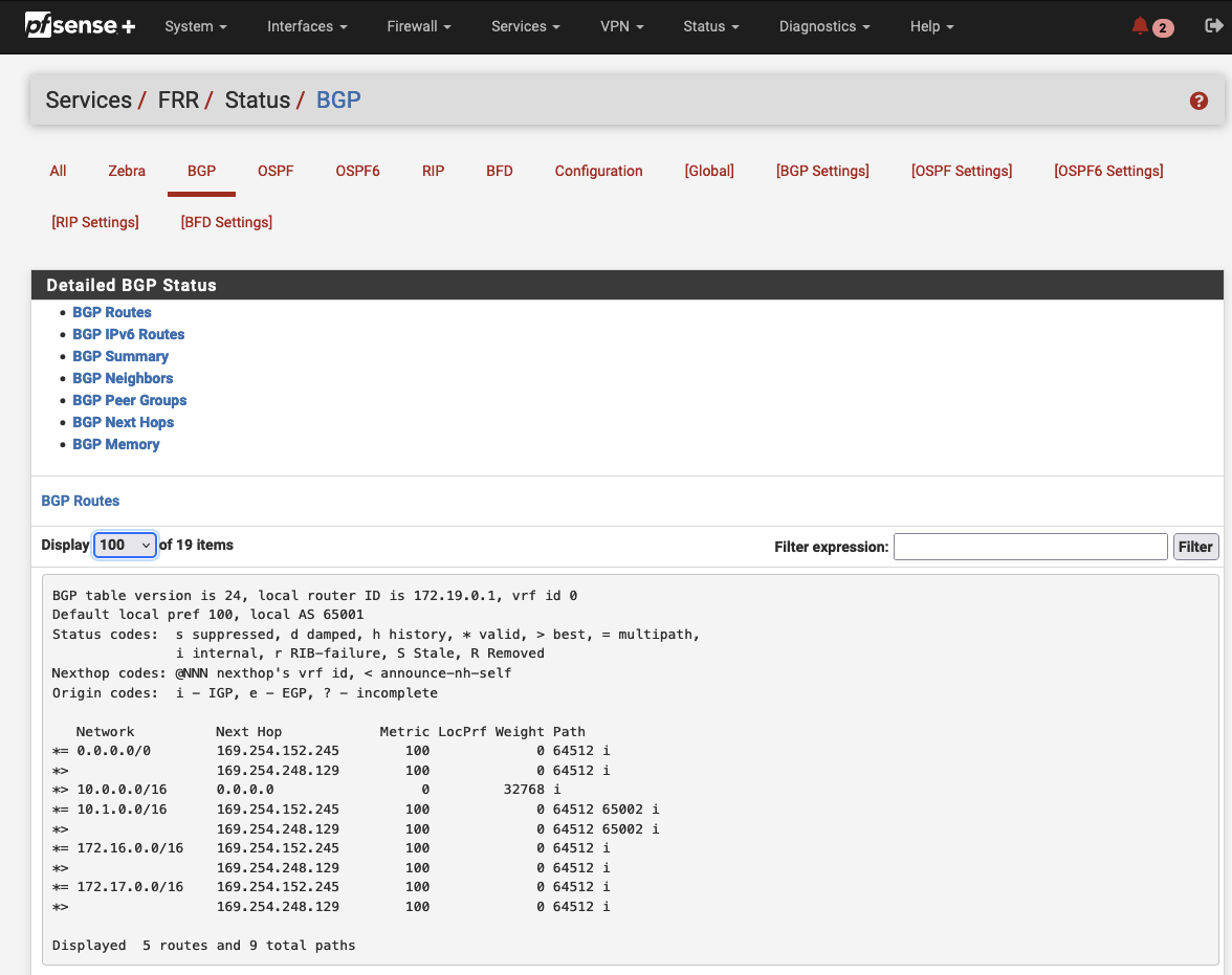
Return to one of the pfSense appliances and navigate to Status -> FRR -> BGP. The first tab with the name BGP routes will display all the routes that are known to pfSense. You will see that the appliances will have knowledge of both the AWS Client VPC and Egress VPC as well as the other on-premises network. This will allow us to establish communication between both on-premises networks via the Transit Gateway.
Test Client/Server Connection
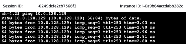
After having configured the pfSense appliance, it is time to test the connection between the client EC2 and server EC2 instance. Open the AWS EC2 Console and select the aws-site-Client EC2 instance. Click on Connect, select the Session Manager tab, and click Connect. Once you have connected to the instance via the Session Manager, execute a ping command to the private IP of one of the on-premises servers.
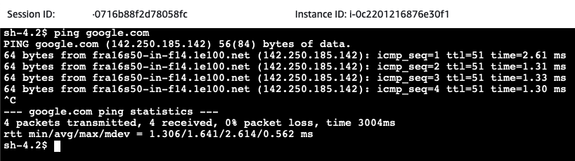
As one of the requirements was to reach the public Internet, we will ping a public domain next. For this example, I will simply ping google.com.
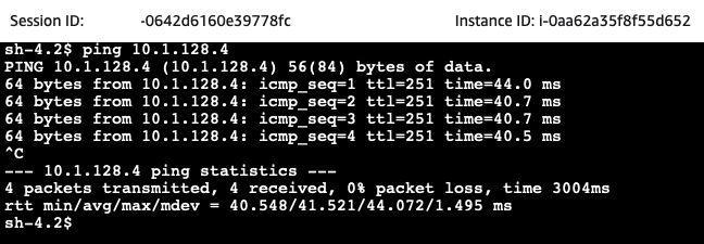
Next, we will test the communication between both on-premises networks. Open the AWS EC2 Console and select the on-premises-1-Server EC2 instance. Click on Connect, select the Session Manager tab, and click Connect. Once you have connected to the instance via the Session Manager, execute a ping command to the private IP of the on-premises-2-Server.
If everything has been set up correctly, the pings should succeed. Congratulations, you just set up a hub and spoke network including Site-to-Site VPN connections between AWS and two (simulated) on-premises networks!
Summary
The architecture that we just implemented is meant to serve as a starting point and an example. There are multiple ways to make the solution more robust and efficient. Firstly, we could make the solution more robust by implementing a second Customer Gateway at each on-premises location to ensure redundancy. Secondly, the VPN and BGP configuration and settings as well as the firewall definitions could be looked at in more detail. To keep this example as short as possible, default settings were used where possible. Lastly, instead of configuring the appliances via the Internet and allowing ingress traffic on port 443, you could leverage AWS System Manager Session Manager Port Forwarding as described in this official blog post.
I hope you had fun and learned something new while working through this example. I am looking forward to your feedback and questions. If you want to take a look at the complete example code please visit my Github.
— Hendrik
Title Photo by Chris King on Unsplash